The Internet Protocol
| Summary |
The Internet Protocol provides a basic delivery
service for transport protocols such as TCP and UDP. IP
is responsible for getting data to its destination host
and network. IP is not reliable, so the effort may fail. |
| Relevant STDs |
2 (http://www.iana.org/
);
3 (includes RFCs 1122 and 1123);
4 (RFC 1812, republished);
5 (includes RFCs 791, 792, 919, 922, 950, and 1112) |
| Relevant RFCs |
781 (Timestamp Option);
791 (Internet Protocol);
815 (Fragmentation Reassembly);
919 (IP Broadcasts);
922 (Broadcasting on Sub-Nets);
950 (Sub-Net Recommendations);
1108 (Security Option);
1112 (IP Multicasting and IGMP v1);
1122 (Host Network Requirements);
1349 (Type-of-Service Flags);
1455 (Data-Link Security TOS Flags);
1812 (Router Requirements);
2113 (Router Alert Option) |
As we learned in
Chapter 1, An Introduction to TCP/IP,
a variety of protocols are used for moving application data
between different systems. We saw that hardware-specific
protocols are used by devices when they need to exchange data
directly, that the Internet Protocol is used to get IP datagrams
across the different network segments to their final
destination, and that TCP and UDP provide transport and
connection management services to the application protocols used
by end-user applications.
Although each of these layers provides unique
and valuable services, the Internet Protocol is perhaps the most
important to the overall operation of the Internet in general,
since it is responsible for getting data from one host to
another.
In this regard, IP can be thought of as being
like a national delivery service that gets packages from a
sender to a recipient, with the sender being oblivious to the
routing and delivery mechanisms used by the delivery agent. The
sender simply hands the package to the delivery agent, who then
moves the package along until it is delivered.
For example, a package that is shipped from New
York to Los Angeles is given to the delivery service (let's say
UPS), with instructions on where the package has to go, although
no instructions are provided on how the package should get to
the destination. The package may have to go through Chicago
first; the delivery agent at the New York UPS office makes that
routing decision. Once the package reaches the Chicago UPS
office, another delivery agent at that facility decides the best
route for the package to take in order to get to Los Angeles
(possibly going through Denver first, for example).
At each juncture, the local delivery agent does
its best to get the package delivered using the shortest
available route. When the package arrives at the Los Angeles
facility, then another agent does its best to get it to the
final destination system, using the destination address provided
with the package to determine the best local routing.
Similarly, it is the function of IP to provide
relaying and delivery decisions whenever an IP datagram has to
be sent across a series of networks in order for it to be
delivered to the final destination. The sending system does not
care how the datagram gets to the destination system, but
instead chooses the best route that is available at that
specific moment. If this involves sending the datagram through
another intermediary system, then that system also makes routing
decisions according to the current condition of the network,
forwarding the data on until it arrives at the destination
system, as specified in the datagram's header.
The IP Standard
IP is defined in RFC 791, which has been
republished as STD 5 (IP is an Internet Standard protocol).
However, RFC 791 contained some vagaries that were clarified in
RFC 1122 (Host Network Requirements). As such, IP
implementations need to incorporate both RFC 791 and RFC 1122 in
order to work reliably and consistently with other
implementations.
RFC 791 begins by stating "The Internet Protocol
is designed for use in interconnected systems of packet-switched
computer communication networks. The Internet protocol provides
for transmitting blocks of data called datagrams from sources to
destinations. The Internet protocol also provides for
fragmentation and reassembly of long datagrams, if necessary,
for transmission through `small packet' networks."
RFC 791 goes on to say "The Internet Protocol is
specifically limited in scope to provide the functions necessary
to deliver a package of bits (an Internet datagram) from a
source to a destination over an interconnected system of
networks. There are no mechanisms to augment end-to-end data
reliability, flow control, sequencing, or other services
commonly found in host-to-host protocols."
That pretty much sums it up. A source system
will send a datagram to a destination system, either directly
(if the destination host is on the local network) or by way of
another system on the local network. If the physical medium that
connects the sending and receiving systems offers enough
capacity, IP will send all of the data in one shot. If this
isn't possible, the data will be broken into fragments that are
small enough for the physical medium to handle.
Once the datagram is sent, IP forgets about it
and moves on to the next datagram. IP does not offer any
error-correction, flow-control, or management services. It just
sends datagrams from one host to another, one network at a time.
TIP: Remember this rule: the Internet Protocol is
responsible only for getting
datagrams from one host to another, one network at a time.
IP Datagrams Versus IP Packets
Hosts on an IP network exchange information
using IP datagrams, which include both the units of data that
contain whatever information is being exchanged and the header
fields that describe that information (as well as describing the
datagram itself). Whenever a device needs to send data to
another system over an IP network, it will do so by creating an
IP datagram, although the datagram is not what gets sent by IP,
at least not in the literal sense.
Instead, IP datagrams get sent as IP packets,
which are used to relay the IP datagrams to the destination
system, one hop at a time. Although in many cases an IP datagram
and an IP packet will be exactly the same, they are conceptually
different entities, which is an important concept for
understanding how IP actually works.
This concept is illustrated in
Figure 2-1. In that example, Ferret needs to send an IP
datagram to Fungi. However, since Fungi is on a remote network,
Ferret has to send the packet containing the datagram to
Sasquatch, who will then send another packet to Fungi.
Figure 2-1.
IP datagrams versus IP packets
|
 |
IP datagrams contain whatever data is being sent
(and the associated IP headers), while IP packets are used to
get the datagram to the destination system (as specified in the
IP headers). These IP packets are sent using the framing
mechanisms defined for the specific network medium in use on the
local network, and are subject to network events such as
fragmentation or loss. However, the datagram itself will always
remain as the original piece of data that was sent by the
original sender, regardless of anything that happens to any of
the packets that are used to relay the datagram.
For example,
Figure 2-2 shows a four-kilobyte datagram that is being sent
from Ferret to Fungi. Since this datagram is too large for the
Ethernet network to send in a single frame, the datagram is
split into four IP packets, each of which are sent as individual
entities in individual Ethernet frames. Once all of the IP
packets are received by the destination system, they will be
reassembled into the original datagram and processed.
Figure 2-2.
Datagram fragmentation overview
|
 |
This model is necessary due to the way that IP
provides a virtual network on top of the different physical
networks that make up the global Internet. Since each of those
networks have different characteristics (such as addressing
mechanisms, frame sizes, and so forth), IP has to provide a
mechanism for forwarding datagrams across those different
networks reliably and cleanly. The datagram concept allows a
host to send whatever data needs to be sent, while the IP packet
allows the datagram to actually get sent across the different
networks according to the characteristics of each of the
intermediary networks.
This concept is fundamental to the design nature
of the Internet Protocol, and is the key to understanding how IP
operates on complex networks.
Local Versus Remote Delivery
The IP header stores the IP addresses of both
the source and destination systems. If the destination system is
on the same physical network as the sending system, then the
sender will attempt to deliver the datagram directly to the
recipient, as shown in
Figure 2-3. In this model, the sender knows that the
recipient is on the same local network, so it transmits the data
directly to the recipient, using the low-level protocols
appropriate for that network medium.
Figure 2-3.
An example of local delivery
|
 |
However, if the two systems are not connected to
the same IP network, then the sender must find another node on
the local network that is able to relay the IP datagram on to
its final destination. This intermediate system would then have
to deliver the datagram if the final recipient was directly
accessible, or it would have to send the datagram on to yet
another intermediary system for subsequent delivery. Eventually,
the datagram would get to the destination system.
A slightly more complex representation of this
can be seen in
Figure 2-4. In that example, the sending system knows that
the destination system is on a remote network, so it locates an
intermediate system that can forward the data on to the final
destination. It then locates the hardware address of the
forwarding system, and passes the data to the intermediate
system using the low-level protocols appropriate for the
underlying medium. The intermediate system then examines the
destination IP address of the datagram, chooses an exit
interface, and sends the data to the final destination system
using the low-level protocols appropriate to that network.
Figure 2-4.
An example of routed delivery
|
 |
The two network models shown in
Figure 2-3 and
Figure 2-4 are both relatively simple, and each represents
the majority of the traffic patterns found on internal corporate
networks. Most networks only have a few segments, with the
target being no more than a handful of hops away from the
originating system.
But once datagrams start travelling over the
Internet, things can get very complex very quickly. Rather than
having to deal with only one or two routers, all of a sudden you
may be looking at a dozen or more hops. However, IP handles
complex networks the same way it handles small networks: one hop
at a time. Eventually, the datagrams will get through. This
concept is illustrated in
Figure 2-5, which shows five different network segments in
between the sending and destination systems.
Figure 2-5.
A complex, multi-hop network path
|
 |
In the example shown in
Figure 2-5, the sender has to give a packet to the local
router, which will send another packet off to a router at the
other end of a modem connection. The remote router then has to
forward the data to yet another router across the carrier
network, which has to send the data to its dial-up peer, which
will finally deliver the datagram to the destination system. In
order for all of this to work, however, each router must be
aware of the path to the destination host, passing the data off
to the next-hop router.
How IP finds remote hosts and networks
Every IP device--regardless of the function it
serves--must have an IP address for every network that it is
connected to. Most systems (such as PCs) only have a single
network connection, and therefore only have a single IP address.
But devices that have multiple network interfaces (such as
routers or high-load devices like file servers) must have a
dedicated IP address for every network connection.
When the IP protocols are loaded into memory, an
inventory is taken of the available interfaces, and a map is
built showing what networks the system is attached to. This map
is called a routing table: it stores information such as the
networks that the node is connected to and the IP address of the
network interface connected to that network.
If a device only has a single interface, then
there will be only one entry in the routing table, showing the
local network and the IP address of the system's own network
interface. But if a device is connected to multiple networks--or
if it is connected to the same network several times--then there
will be multiple entries in the routing table.
TIP: In reality, just about every IP device also
has a "loopback" network, used for testing and debugging
purposes. The loopback network is always numbered 127.0.0.0,
while the loopback interface always has the IP address of
127.0.0.1. This means that routing tables will generally
show at least two entries: one for the physical connection
and one for the loopback network.
When a system has to send a datagram to another
system, it looks at the routing table and finds the appropriate
network interface to send the outbound traffic through. For
example, the router shown in the top-left corner of
Figure 2-5 has two network connections: an Ethernet link
with the IP address of 192.168.10.3 and a serial connection with
an IP address of 192.168.100.1. If this router needed to send
data to 192.168.10.10, then it would use the Ethernet interface
for that traffic. If it needed to send datagrams to
192.168.100.100, it would use the serial interface.
Table 2-1 shows what the router's routing table would look
like based on this information.
Table 2-1:
The Default Routing Table for
192.168.10.1
|
Destination Network |
Interface/Router |
|
127.0.0.0 (loopback network) |
127.0.0.1 (loopback interface) |
|
192.168.10.0 (local Ethernet
network) |
192.168.10.1 (local Ethernet
interface) |
|
192.168.100.0 (local serial network) |
192.168.100.1 (local serial
interface) |
However, such a routing table would not provide
any information about any remote networks or devices. In order
for the router to send an IP datagram to 172.16.100.2, it would
need to have an entry in the routing table for the 172.16.100.0
network. Systems are informed of these details by adding entries
to the routing table. Most TCP/IP packages provide end-user
tools that allow you to manually create and delete routing
entries for specific networks and hosts. Using such a tool, you
could inform the router that the 172.16.100.0 network is
accessible via the router at 192.168.100.100. Once done, the
routing table for the local router would be similar to the one
shown in
Table 2-2.
Table 2-2:
The Routing Table for 192.168.10.1
with a Remote Route Added
|
Destination Network |
Interface/Router |
|
127.0.0.0 (loopback network) |
127.0.0.1 (loopback interface) |
|
192.168.10.0 (local Ethernet
network) |
192.168.10.1 (local Ethernet
interface) |
|
192.168.100.0 (local serial network) |
192.168.100.1 (local serial
interface) |
|
172.16.0.0 (remote carrier network) |
192.168.100.100 (next-hop router) |
Since the router already knows how to send
datagrams to 192.168.100.100, it now knows to send all datagrams
for 172.16.100.2 to 192.168.100.100, under the assumption that
the remote router would forward the packets for delivery. By
adding entries for each network segment to the local routing
table, you would be able to tell every device how to get
datagrams to remote segments of the network. Such a routing
table might look the one shown in
Table 2-3.
Table 2-3:
Complete Routing Table for
192.168.10.1, Showing Entire Network
|
Destination Network |
Interface/Router |
|
127.0.0.0 (loopback network) |
127.0.0.1 (loopback interface) |
|
192.168.10.0 (local Ethernet
network) |
192.168.10.1 (local Ethernet
interface) |
|
192.168.100.0 (local serial network) |
192.168.100.1 (local serial
interface) |
|
172.16.100.0 (remote carrier
network) |
192.168.100.100 (next-hop router) |
|
192.168.110.0 (remote serial
network) |
192.168.100.100 (next-hop router) |
|
192.168.30.0 (remote Ethernet
network) |
192.168.100.100 (next-hop router) |
Unfortunately, you would have to add entries for
every segment of the network to every device on the network in
order for everything to function properly. Each router would
have to have a map showing every network and the routers that
were to be used for that network. This task can be a lot of
work, and is also highly prone to human error.
Several application protocols can be used to
build maps of the network and distribute them to all of your
systems without human intervention. The most popular of these
for private networks is the Routing Information Protocol (RIP),
which uses UDP broadcasts to distribute routing tables every
thirty seconds. Another popular protocol is Open Shortest Path
First (OSPF), which provides the same basic functionality as RIP
but with more detail and less overhead. For external networks,
neither of these protocols work well enough to support a
significant number of networks, and other protocols (such as the
Border Gateway Protocol) are more common for those environments.
In common practice, most network administrators
run these dynamic routing protocols only on their routers (but
not on their hosts) since they tend to consume a lot of CPU
cycles, memory, and network bandwidth. They then define
"default" routes at the hosts, pointing them to the router(s)
that serve the local network that the host is attached to. By
using this model, clients need to keep only one entry in their
routing tables, while the dedicated routers worry about keeping
track of the overall network topology.
Table 2-4 shows what this might look like from the
perspective of our example router. Notice that it has routing
entries only for the locally attached networks, and that it now
knows to send any other datagrams to
the default router at 192.168.100.100. That router would then
forward all of the datagrams that it gets to its default router
as well.
Table 2-4:
A Simplified Routing Table for
192.168.10.1
|
Destination Network |
Interface/Router |
|
127.0.0.0 (loopback network) |
127.0.0.1 (loopback interface) |
|
192.168.10.0 (local Ethernet
network) |
192.168.10.1 (local Ethernet
interface) |
|
192.168.100.0 (local serial network) |
192.168.100.1 (local serial
interface) |
|
0.0.0.0 (default route) |
192.168.100.100 (next-hop router) |
Default routes can be built manually (using the
tools provided with the IP software in use on the local system),
or can be assigned during system boot (using a protocol such as
BOOTP or DHCP). In addition, a protocol called Router Discovery
can provide network devices with default route information
dynamically, updating the devices' routing tables as the network
topology changes.
The examples shown earlier illustrate that
managing routing tables can be complex, even with relatively
small networks. Unfortunately, the Internet consists of several
hundred thousand such networks. If all of the routers connecting
these networks together had to be tracked by all of the other
routers, there would be so much router-management traffic that
nothing else could get through. The Internet would collapse
under its own weight.
Route aggregation
New address assignment schemes are being
deployed that allow routes to be aggregated together. Now, when
you request a block of Internet addresses from your Internet
Service Provider, the ISP must assign one from a larger block
that has already been assigned to them. This allows routing to
happen at a much higher level. Rather than ISPs having to track
and advertise thousands of network routes, they only have to
advertise a few super-routes.
The ISP will still have to track all of the
networks that are under it, but it won't have to advertise them
to other ISPs. This feature cuts down on the amount of backbone
router-update traffic immensely, without losing any
functionality.
Geography-based aggregation schemes are also
being deployed. For example, any network that begins with 194 is
somewhere in Europe. This simple assignment allows major routers
on the Internet to simply forward traffic for any network that
begins with 194 to the backbone routers in Europe. Those routers
will then forward the datagrams to the appropriate regional ISP,
who will then relay the datagrams on to their final destination.
This process is conceptually similar to the way
that area codes and prefixes help the phone company route a
call. Telephone switches can route a long-distance call simply
by examining the area code. The main switches in the remote area
code will then examine the telephone number's three-digit
prefix, and route the call to the appropriate central office. By
the time you finish dialing the last four digits of the phone
number, the call is practically already established.
By using aggregated routing techniques, IP
datagrams can be moved around the Internet in much the same
manner. Aggregation allows routers to use much smaller tables
(around 50,000 routes instead of two million routes), which
keeps CPU and memory requirements as low as possible, which, in
turn, allows performance to be higher than it otherwise would be
if every router had to keep track of every network's router
path.
For more information about hierarchical routing,
refer to "Classless Inter-Domain Routing (CIDR)" in
Appendix B,
IP Addressing Fundamentals.
Datagram Independence
In the preceding section, we used an analogy of
a telephone number to illustrate how routers are able to route
datagrams to their final destination quickly, based on the
destination IP address. However, we should also point out that
IP packets are not at all like telephone calls.
Telephone networks use the concept of "circuits"
to establish a point-to-point connection between two users. When
two people establish a telephone call, a dedicated
point-to-point connection is established and is preserved for
the duration of the call. In contrast, IP networks treat every
individual IP datagram as a totally unique entity, each of which
is free to travel across whatever route is most suitable at that
moment.
For example, if a user were to retrieve a
document from a remote web server, the server would probably
need to generate several IP datagrams in order to return the
requested material. Each of these datagrams is considered to be
a unique and separate entity, totally unrelated to the datagrams
sent before or after.
Each of these datagrams may take whatever path
is deemed most appropriate by the routers that are forwarding
them along. Whereas the first datagram sent from the web server
to the requesting client may travel across an underground
fiber-optic cable, the second datagram may be sent across a
satellite link, while a third may travel over a conventional
network. This concept is illustrated in
Figure 2-6.
Figure 2-6.
Every IP datagram is an individual
entity and may take a different route
|
 |
These routing decisions are made by the routers
in between the source and destination systems. As the network
changes, the routers that are moving datagrams around will have
to adapt to the changing environment. Many things can cause the
network to change: network cables can be ripped up, or
downstream routers can become too busy to service a request, or
any number of other events can happen to cause a route to become
unavailable.
A result of this independence is that datagrams
may arrive at their destination out of sequence, since one of
them may have gone over a fast network, while another may have
been sent over a slow network. In addition, sometimes datagrams
get duplicated, causing multiple copies of the same packet to
arrive at the destination system.
This architecture is purposefully designed into
IP: one of the original design goals for the Internet Protocol
was for it to be able to survive large-scale network outages in
case of severe damage caused during war-time. By allowing each
datagram to travel along the most-available path, every
datagram's chances of survival increases dramatically. IP does
not care if some of them happen to arrive out of sequence, get
lost in transit, or even arrive multiple times; its job is to
move the datagram, not to keep track of it. Higher-level
protocols deal with any problems that result from these events.
Furthermore, by treating every datagram as an
individual entity, the network itself is relieved of the
responsibility of having to track every connection. This means
that the devices on the network can focus on moving datagrams
along, and do not have to watch for the beginning and end of
every web browser's session. This feature allows overall
performance to be as high as the hardware will allow, with as
little memory and CPU requirements as possible.
Housekeeping and Maintenance
Every system that receives a packet--whether the
system is the final destination or a router along the delivery
path--will inspect it. If the packet has become corrupt or has
experienced some other form of temporary failure, then the
packet will be destroyed right then and there. Whenever one of
these transient errors occurs, the datagram is destroyed rather
than being forwarded on.
However, if a problem occurs that is
semi-permanent--for example, if the current device does not have
a routing table entry for the destination network, or if the
packet does not meet certain criteria for forwarding across the
next-hop network--then IP may call upon the Internet Control
Message Protocol (ICMP) to return an error message back to the
original sender, informing them of the failure. Although the
datagram will still be destroyed by the last-hop device, it will
also inform the sender of the problem, thereby allowing it to
correct whatever condition was causing the failure to occur.
This distinction between transient and
semi-permanent failures is important. Transient errors are
caused by no fault of the sender (such as can happen when the
Time-to-Live timer expires, or a checksum is miscalculated),
while semi-permanent failures are problems with the packet or
network that will always prevent delivery from occurring over
this path. In the latter case, it is best either to inform the
sender of the problem so that it can take whatever corrective
actions are required, or to notify the application that tried to
send the data of the problem.
Chapter 5,
The Internet Control Message Protocol,
discusses the error messages that are generated by ICMP whenever
a semi-permanent problem is encountered. However, the remainder
of this section also discusses some of the transient problems
that may occur with IP delivery in particular.
Header checksums
Part of this integrity-checking service is
handled through the use of a checksum applied against the IP
datagram's header (but not against the
data inside of the IP datagram). Every device that receives an
IP datagram must examine the IP header and compare that
information with the value stored in the header's checksum
field. If the values do not match, then the datagram is assumed
to be corrupt and is discarded immediately.
The data portion of the IP datagram is not
verified, for three reasons. First of all, a device would have
to examine the entire datagram to verify the contents. This
process would require additional CPU processing time, which is
more often than not going to be a waste of time.
Second, the data portion of an IP datagram
always consists of a higher-level datagram, such as those
generated by TCP and UDP. Since these protocols provide their
own error-checking routines, the recipient system will have to
conduct this verification effort anyway. The theory is that
datagrams will move faster if routers do not have to verify
their contents, a task which will be handled by the destination
system anyway.
Finally, some application protocols are capable
of working with partially corrupt data. In those cases, IP would
actually be performing a disservice if it were to throw away
datagrams with invalid checksums, since the application protocol
would never get it. Granted, most applications do not work this
way, but most applications will also utilize some form of
error-correction service to keep this from becoming a problem.
Time-to-Live
Another validation service provided by IP is
checking to see if a datagram has outlived its usefulness. This
is achieved through a Time-to-Live field provided in the IP
datagram's header. When a system generates an IP packet, it
stores a value in the Time-to-Live header field. Every system
that forwards the packet decreases the value of the Time-to-Live
field by one, before sending the datagram on. If the
Time-to-Live value reaches zero before the datagram gets to its
final destination, then the packet is destroyed.
The purpose of the Time-to-Live field is to keep
datagrams that are caught in an undeliverable loop from tying up
network resources. Let's assume that a pair of routers both have
bad information in their routing table, with each system
pointing to the other for final delivery. In this environment, a
packet would be sent from one router to the other, which would
then return the packet, with this process repeating forever.
Meanwhile, more packets may be introduced to this network from
external devices, and after a while, the network could become
saturated.
But by using a Time-to-Live field, each of these
routers would decrement the value by one every time it forwarded
a packet. Eventually the Time-to-Live value would reach zero,
allowing the datagram to be destroyed. This safeguard prevents
routing loops from causing network meltdowns.
The strict definition of the Time-to-Live field
states that the value is a measure of time in seconds, or any
forwarding act that took less than one second to perform.
However, there are very few Internet routers that require a full
second to perform forwarding, so this definition is somewhat
misrepresentative. In actual practice, the Time-to-Live value is
decremented for every hop, regardless of the actual time
required to forward a datagram from one network segment to
another.
It is also important to note that an ICMP
failure-notification message gets sent back to the original
sender when the Time-to-Live value reaches zero. For more
information on this error message, refer to "Time Exceeded" in
Chapter 5.
The default value for the Time-to-Live field
should be set to 64 according to the Assigned Numbers registry (http://www.iana.org/
). In addition, some of the higher-layer protocols also have
default Time-to-Live values that they are supposed to use (such
as 64 for TCP, and 1 for IGMP). These values are really only
suggestions, however, and different implementations use
different values, with some systems setting the Time-to-Live on
all outgoing IP datagrams as high as 255.
Fragmentation and Reassembly
Every network has certain characteristics that
are specific to the medium in use on that network. One of the
most important characteristics is the maximum amount of data
that a network can carry in a single frame (called the Maximum
Transmission Unit, or "MTU"). For example, Ethernet can pass
only 1500 bytes in a single frame, while the typical MTU for
16-megabit Token Ring is 17,914 bytes per frame.
RFC 791 specifies that the maximum allowed MTU
size is 65,535 bytes, and that the minimum allowed MTU size is
68 bytes. No network should advertise or attempt to use a value
that is greater or lesser than either of those values. Several
RFCs define the specific default MTU values that are to be used
with different networking topologies.
Table 2-5 lists the common MTU sizes for the most-common
media types, and also lists the RFCs (or other sources) that
define the default MTU sizes for those topologies.
Table 2-5:
Common MTU Sizes and the Related RFCs
|
Topology |
MTU (in bytes) |
Defined By |
|
Hyperchannel |
65,535 |
RFC 1374 |
|
16 MB/s Token Ring |
17,914 |
IBM |
|
802.4 Token Bus |
8,166 |
RFC 1042 |
|
4 MBs Token Ring |
4,464 |
RFC 1042 |
|
FDDI |
4,352 |
RFC 1390 |
|
DIX Ethernet |
1,500 |
RFC 894 |
|
Point-to-Point Protocol (PPP) |
1,500 |
RFC 1548 |
|
802.3 Ethernet |
1,492 |
RFC 1042 |
|
Serial-Line IP (SLIP) |
1,006 |
RFC 1055 |
|
X.25 & ISDN |
576 |
RFC 1356 |
|
ARCnet |
508 |
RFC 1051 |
Since an IP datagram can be forwarded across any
route available, every IP packet that gets generated by a
forwarding device has to fit the packet within the available MTU
space of the underlying medium used on the transient network. If
you're on an Ethernet network, then IP packets have to be 1500
bytes or smaller in order for them to be carried across that
network as discrete entities, regardless of the size of the
original datagram.
There are really two concepts at work here: the
size of the original IP datagram and the size of the packets
that are used to relay the datagram from the source to the
destination. If the datagram is too large for the sending
system's local MTU, then that system has to fragment the
datagram into multiple packets for local delivery to occur. In
addition, if any of those IP packets are too large to cross
another network segment somewhere between the sender and final
recipient, then the packets must be fragmented by that router as
well, allowing them to be sent across that network.
On an isolated network, size rarely matters
since all of the systems on that network will share the same
maximum frame size (a server and a client can both use at most
1500-byte datagrams, if both of them are on the same Ethernet
segment). However, once you begin to mix different network media
together, size becomes very important.
For example, suppose that a web server were on a
Token Ring network that used 4,464-byte packets, while the end
users were on a separate Ethernet segment that used 1500-byte
packets. The TCP/IP software on the server would generate IP
datagrams (and packets) that were 4,464 bytes long (according to
the MTU characteristics of the local network), but in order for
the IP datagrams to get to the client, the router in between
these two segments would have to fragment the large packets into
smaller packets that were small enough to move over the Ethernet
network, as illustrated in
Figure 2-7.
Figure 2-7.
One 4,464-byte packet being split
into four 1500-byte packets
|
 |
During the act of fragmentation, the router will
do several things. First of all, it will examine the size of the
data that is stored in the original packet, and then it will
create as many fragments as are needed to move the original
packet's data across the smaller segment. In the example shown
in
Figure 2-7, a single 4,464-byte IP packet would require four
IP packets in order to travel across the 1500-byte Ethernet (the
mathematics behind this process will be explained in a moment).
TIP: In this example, the destination host may not
be able to reassemble the original datagram, since the
datagram is larger than the MTU of the local Ethernet
connection. RFC 1122 states that hosts must be able to
reassemble datagrams of at least 576 bytes, and should be
able to reassemble datagrams that are "greater than or equal
to the MTU of the connected network(s)." In this case, the
local MTU is 1500 bytes, although the original datagram was
four kilobytes, so it is possible that the destination
system would be unable to reassemble the original datagram.
Although most systems do not have problems with this, it
should not come as a surprise if a wireless hand-held device
cannot reassemble 65 KB datagrams sent from high-speed
servers.
When the original 4,464-byte packet was
fragmented, the headers of each of the new 1500-byte IP packets
would be given whatever information was found in the original
packet's header, including the source and the destination IP
addresses, the Time-to-Live value, the Type-of-Service flags,
and so on.
With regards to fragmentation in particular, the
most important of these fields is the Fragmentation Identifier
field, which is used to mark each of the fragments as belonging
to the same original IP datagram. The Fragmentation Identifier
field is really more of a Datagram Identifier, and is a 16-bit
"serial number" that gets generated by the sending system
whenever a datagram gets created. Whenever a packet gets
fragmented, all of the resulting fragments use the original
datagram's Fragmentation Identifier, and the destination system
uses this information to collect all of the fragments together,
and then reassemble the original datagram into its original
form.
In addition, two fields within each of the
fragments' IP headers will also be set, to reflect the fact that
fragmentation has occurred. The fields that get set are the
Fragmentation Offset and a Fragment Flags field (the latter is
used to provide ordering and reassembly clues to the destination
system).
- Fragmentation Offset
- This field is used to indicate the
byte-range of the original datagram that a specific fragment
provides. However, only the starting
position of the byte-range is provided in this field (the
remainder of the packet is assumed to contain the rest of
that fragment). This starting position is stored in terms of
eight-byte (64-bit) blocks of data. The Fragmentation Offset
identifier allows the receiving system to re-order the
fragments into their proper sequence once all of the
fragments have arrived.
- Fragment Flags
- This field provides clues as to the
current fragmentation status (if any). There are three
one-bit flags, although only the last two are currently
used. The first bit is reserved for future use and must
always be set to 0. The second bit indicates whether or not
fragmentation is allowed (0 means fragmentation is allowed
and 1 means do not fragment). The third and final bit is
used to indicate whether a current fragment is the last (0),
or if more fragments will follow this one (1).
In addition to these changes, the Total Packet
Length field for each of the newly minted IP packets also gets
set according to the size of the fragments (rather than the size
of the original datagram).
The resulting IP packets are then sent over the
Internet as independent entities, just as if they had originally
been created that way. Fragments are not reassembled until they
reach the destination system. Once they reach the final
destination, however, they are reassembled by the IP software
running on the destination system, where they are combined back
into their original datagram form. Once the original datagram
has been reassembled, the IP datagram's data is forwarded to the
appropriate transport protocol for subsequent processing.
There are a few rules that you must remember
when trying to understand how IP fragments get created:
- Fragmentation only occurs on the data
portion of a packet.
- Packet headers are
not included in the fragmentation
process. If the original datagram is 4,464 bytes long, then
at least 20 bytes of that datagram are being used to store
header information, meaning that the data portion is 4,444
bytes long. This 4,444 bytes is what will get fragmented.
- Each new fragment results in a new
packet that requires its own IP headers, which consume at
least 20 bytes in each new packet generated for a fragment.
The IP software must take this factor into consideration
when it determines the maximum amount of payload data that
can be accommodated in each fragment, and thus the number of
fragments that will be required for a particular MTU.
- Fragmentation must occur on an
eight-byte boundary. If a datagram contains 256 bytes of
data, but only 250 bytes can fit into a fragment, then the
first fragment contains only 248 bytes of data (248 is the
largest number divisible by eight that's less than 250). The
remaining 8 bytes (256 - 248 = 8) will be sent in the next
fragment.
- The Fragmentation Offset field is
used to indicate which parts of the original datagram are in
each fragment, by storing the byte count in quantities of
eight-byte blocks. Rather than indicating that the starting
position for a fragment's data is "248 bytes," the
Fragmentation Offset field will show "31 blocks" (248 / 8 =
31). Also, note that the block count starts with 0 and not
1. This means that the 32nd block will be numbered 31
instead of 32.
As shown in
Figure 2-7, in order for the original 4,464-byte IP datagram
to be sent across the Ethernet network segment, four IP
fragments will have to be created. Each of the new packets will
contain an IP header (copied from the original datagram's
header), plus however much data they could carry (although the
quantity has to be divisible by eight). The result is four
unique fragments, as shown in
Figure 2-8.
The relevant fields from the original IP packet
are shown in
Table 2-6.
Table 2-6:
Headers from the Original 4,464-byte
Packet
|
Fragment |
Fragment
Identifier |
Reserved
Flag |
May Fragment
Flag |
More Fragment
Flags |
Fragment
Offset |
Packet
Length |
|
1 |
321 |
0 |
0 |
0 |
0 |
4,464 |
Figure 2-8.
The mathematics of datagram
fragmentation
|
 |
After converting the single 4,464-byte IP packet
into four 1500-byte IP fragments, the headers of each fragment
will appear as shown in
Table 2-7.
Table 2-7:
Headers from Four 1500-byte Fragments
|
Fragment |
Fragment
Identifier |
Reserved
Flag |
May Fragment
Flag |
More Fragment
Flags |
Fragment
Offset |
Packet
Length |
|
1 |
321 |
0 |
0 |
1 |
0 |
1,500 |
|
2 |
321 |
0 |
0 |
1 |
185 |
1,500 |
|
3 |
321 |
0 |
0 |
1 |
370 |
1,500 |
|
4 |
321 |
0 |
0 |
0 |
555 |
24 |
Each of the fragments contains the following
header information:
- Each fragment belongs to the same
original datagram, so each of them share the same "serial
number" in the Fragmentation Identifier field (321 in this
case).
- The first bit in the 3-bit Flags
field is reserved, and must be marked 0.
- Each packet may be fragmented
further, so the "May Fragment" flags are marked 0.
- The "More Fragments" flag is used to
indicate if more fragments are following after this
fragment. Since the first three fragments all have another
fragment coming behind them, they all have the More
Fragments flag marked 1, while the last fragment identifies
the end of the set by having a 0 in this field.
- Since the first fragment marks the
beginning of the original data, the Fragment Offset field
starts at 0. Since the first fragment held 1,480 bytes of
data, the second fragment would have its Fragmentation
Offset field set to 185 (1480 / 8 = 185). The second
fragment was also able to store 1,480 bytes, so the Fragment
Offset flag for the third packet will be set to 370 ((1480 ×
2) / 8 = 370). The third fragment was also able to hold
1,480 bytes, so the fourth fragment's Fragment Offset flag
will be set to 555 ((1480 × 3) / 8 = 555).
- In addition, each new IP packet
created during the fragmentation process will also have its
Total Packet Length field set to the size of the resulting
IP packets, rather than set to the size of the original IP
datagram.
In order for the destination system to
reassemble the datagram, it must read the fragmentation-specific
headers in each of the fragments as they arrive and order them
into their correct sequence (as indicated by the Fragment Offset
field). Since each fragment may arrive out of sequence (due to a
slower link, a down segment, or whatever), the destination
system has to store each fragment in memory until all of them
have arrived before they can be rearranged and the data
processed.
Once all of the segments have been received, the
system will examine their headers and find the fragment whose
Fragment Offset is 0. The IP software will then read the data
portion of the IP packet containing that fragment, recording the
number of eight-byte blocks that it finds. Then it will locate
the fragment that shows the Fragment Offset needed to continue
reading the data, and then read that fragment's data into
memory. This process will continue until all of the data has
been read from all of the packets. Once a packet has been read
that has the "More Fragments" flag set to 0--and if each of the
Fragment Offset fields matches up without leaving any holes in
the final datagram--then the process is complete.
If all of the fragments do not arrive within the
predefined time (normally 60 seconds on most Unix-like systems),
then all of the fragments will be destroyed, and an error
message will be sent to the original sender, using the ICMP
"Time Exceeded" error message. For more information on this
error message, refer to "Time Exceeded" in Chapter 5.
This process can get fairly tricky, and it may
seem like an awful lot of overhead. However, there are many
benefits offered by fragmentation. First and foremost,
fragmentation allows IP to use whatever packet sizes are
required by the underlying medium. Furthermore, any traffic that
is local to your own network probably won't require
fragmentation, so you can use large packets on your local
network. If IP were forced to use a lowest-common-denominator
approach of very small packets for all data, then local
performance would always be miserable. But by using a flexible
MTU size, the local network can run at full speed, with
fragmentation only occurring whenever large datagrams must leave
the local network.
TIP: RFC 791 states that all systems must be able
to send an IP datagram of at least 576 bytes. Indeed, many
of the early IP routers required that IP datagrams be cut
into 576-byte fragments if they were to be forwarded over a
different media (regardless of that media's MTU capacity).
In addition, there are some techniques that can
be used by a sending system to determine the most efficient
segment size when sending data to a remote network, thereby
preventing fragmentation from occurring. TCP connections use a
"Maximum Segment Size" header option that can be used to
determine the MTU of the remote network, and most IP systems
implement a technology called "Path MTU Discovery" that allows
them to detect the largest available MTU on the end-to-end
connection. For more information on the Maximum Segment Size
option, refer to "Maximum Segment Size" in
Chapter 7,
The Transmission Control Protocol.
For more information on Path MTU Discovery, refer to "Notes on
Path MTU Discovery" in Chapter 5.
Prioritization and Service-Based Routing
One of the key differences between IP and other
networking protocols is that IP offers direct support for
prioritization, allowing network hosts and routers to send
important packets before less important packets. This feature is
particularly crucial with applications that are sensitive to
high levels of delay resulting from network congestion.
For example, assume that an organization has two
high-speed networks that are interconnected by a relatively slow
wide area network (WAN), and that a lot of data has to cross the
WAN frequently. In this example, the routers could forward data
across the WAN only at whatever rate was allowed by the WAN
itself. If the WAN were fixed at a maximum throughput of 256
KB/s, then the routers on the WAN could only send 262,144 bits
across the WAN in a single second. This may be plenty of
bandwidth for a few terminal emulation sessions--or even for a
couple of simultaneous database updates--but it would not be
enough for several simultaneous streaming video feeds in
conjunction with those other applications.
The problem is that the routers just wouldn't be
able to forward enough data across the WAN for all of the
applications to work smoothly. The routers would have to start
dropping packets once their buffers began filling up or as the
queuing delays exceeded the maximum Time-to-Live values on some
of the packets. UDP-based applications may not care much about
these dropped packets, but TCP-based applications care very much
about lost packets. They would attempt to resend any data that
had not yet been acknowledged, and if congestion was sustained
for a long period of time, then those applications would
eventually just timeout.
This may not matter with some applications, but
it would be a very big deal with some others, particularly those
that are crucial to the operation of the business itself. For
example, if users were unable to enter sales orders into a
remote database, the problem would be somewhat greater than if
they were unable to access a recreational video.
In order to ensure that congestion doesn't break
the mission-critical applications on your network, IP supports
two key concepts: prioritization and type-of-service handling.
Every IP datagram has an 8-bit field (called the "TOS byte")
that consists of a three-bit precedence field used for
prioritization and a four-bit field that indicates specific
handling characters desired for a datagram (the last bit is
currently unused).
By using three bits for precedence, IP has eight
levels of prioritization (0 through 7), which provide eight
distinct priority levels to all IP traffic.
Table 2-8 lists the values of the Precedence field and their
meaning as defined in RFC 791, with the highest priority level
being 7 and the lowest being 0.
Table 2-8:
The Precedence Flags and Their
Meaning.
|
Precedence |
Definition |
|
0 |
Routine (normal) |
|
1 |
Priority |
|
2 |
Immediate |
|
3 |
Flash |
|
4 |
Flash Override |
|
5 |
Critical |
|
6 |
Internetwork Control |
|
7 |
Network Control |
Using these priority values, you could assign
database applications a higher priority level than the streaming
video traffic. The routers would then sift through data that was
waiting in the queue, sending the higher priority traffic before
sending the lower priority traffic. In this model, the database
traffic would be sent out first, while the streaming video
traffic would be forced to wait until bandwidth was available.
Your mission-critical applications would continue to function
smoothly, while the less-critical applications would take a back
seat, possibly suffering dramatic performance losses.
The remaining four bits of the TOS byte provide
administrators with the ability to implement per-datagram
routing based on the characteristics of the datagram's data.
Thus, an IP datagram that contains Usenet news traffic can be
marked as desiring a "low-cost" service, while Telnet traffic
can be marked as desiring a "low-latency" service.
Originally, there were only three types of
service defined in RFC 791. These services were identified with
unique bits that were either on or off, depending on whether or
not the specific type of service was desired. However, this
interpretation was modified by RFC 1349, which added a fourth
service class, and which also stated that the bits were to be
interpreted as numeric values rather than independent flags. By
making them numeric, the four bits provided for a maximum of
sixteen possible values (0 through 15), rather than four
distinct options (although the values cannot be combined and
must be used independently).
There are a number of predefined Type-of-Service
values that are registered with the Internet Assigned Numbers
Authority (IANA). Some of the more common registered values are
shown in
Table 2-9.
For a detailed listing of all of the
Type-of-Service values that are currently registered, refer to
the IANA's online registry (accessible at
http://www.isi.edu/in-notes/iana/assignments/ip-parameters).
Table 2-9:
Type-of-Service Values and Their
Meaning
|
Value |
Service |
Description |
|
0 |
Normal |
When all of the Type-of-Service
flags are off, the IP datagram is to be treated as a
normal datagram, and is not to be given any special
handling. Almost all IP datagrams are marked with all
zeroes in the Type-of-Service field. |
|
1 |
Minimize Delay |
The Delay flag is used to request
that IP route this packet over a network that provides
lower latency than normal. This may be useful for an
application such as Telnet, where the user would want to
see their keystrokes echoed back to them quickly. The
Delay flag may be set to either 0 (normal) or 1 (low
delay). |
|
2 |
Maximize Throughput |
The Throughput flag is used to
request that IP route this packet over a network that
provides higher throughput than normal. This may be
useful for an application such as FTP, where the user
would want to download a lot of data very quickly. The
Throughput flag may be set to 0 (normal) or 1 (high
throughput). |
|
4 |
Maximize Reliability |
The Reliability flag is used to
request that IP route this packet over a network that
provides the most reliable service (perhaps as indicated
by overall up-time, or by the number of secondary
routes). This may be useful for an application such as
NFS, where the user would want to be able to open a
database on a remote server without worrying about a
network failure. The Reliability flag may be set to 0
(normal) or 1 (high reliability). |
|
8 |
Minimize Cost |
The Cost flag was added by RFC 1349
and was not defined in RFC 791. For this reason, many
systems do not recognize or use it. The Cost flag is
used to request that IP route this packet over the least
expensive route available. This may be useful for an
application such as NNTP news, where the user would not
need data very quickly. The Cost flag may be set to 0
(normal) or 1 (low cost). |
|
15 |
Maximize Security |
RFC 1455--an experimental
specification for data-link layer security--states that
this flag is used to request that IP route this packet
over the most secure path possible. This may be useful
with applications that exchange sensitive data over the
open Internet. Since RFC 1455 is experimental, most
vendors do not support this setting. |
In addition, the IANA's online registry also
defines a variety of default Type-of-Service values that
specific types of applications should use. Some of the more
common application protocols and their suggested Type-of-Service
values are shown in
Table 2-10. For a detailed listing of all of the suggested
default Type-of-Service values, refer to the IANA's online
registry (accessible at
http://www.isi.edu/in-notes/iana/assignments/ip-parameters).
Table 2-10:
Suggested Type-of-Service Values for
Common Application Protocols
|
Application Protocol |
Suggested TOS Value |
|
Telnet |
8 |
|
FTP Control Channel |
8 |
|
FTP Data Channel |
4 |
|
Trivial FTP |
8 |
|
SMTP Commands |
8 |
|
SMTP Data |
4 |
|
DNS UDP Query |
8 |
|
DNS TCP Query |
0 |
|
DNS Zone Transfer |
4 |
|
NNTP |
1 |
|
ICMP Error Messages |
0 |
|
SNMP |
2 |
It is important to note that not all of the
TCP/IP products on the market today use these values. Indeed,
many implementations do not even offer any mechanisms for
setting these values, and will not treat packets that are
flagged with these values any differently than packets that are
marked for "normal" delivery. However, most of the Unix variants
on the market today (including Linux, BSD, and Digital Unix) do
support these values, and set the appropriate suggested default
values for each of the major applications.
Administrators that have complex networks with
multiple routing paths can use these type of service flags in
conjunction with TOS-aware routers to provide deterministic
routing services across their network. For example, an
administrator might wish to send low-latency datagrams through a
terrestial fiber-optic connection rather than through a
satellite link. Conversely, an administrator might wish to send
a low-cost datagram through a slower (but fixed-cost)
connection, rather than take up bandwidth on a satellite
connection.
By combining the type of service flags with the
prioritization bits, it is possible to dictate very explicit
types of behavior with certain types of data. For example, you
could define network filters that mark all Lotus Notes packets
as medium priority and tag them with the low-latency TOS flag.
This would not only provide your Notes users with preferential
service over less-critical traffic, but it would also cause that
traffic to be routed over faster network segments. Conversely,
you could also define another set of filters that marked all
streaming video traffic as lower priority and also enable the
high-bandwidth TOS flag, forcing that traffic to use a more
appropriate route.
As long as you own the end-to-end connection
between the source and destination systems, you can pretty much
do whatever you want with these flags, and you should be able to
queue and route those datagrams according to the flags that you
set. Keep in mind, however, that most ISPs will not treat these
datagrams any different than unmarked datagrams (otherwise,
you'd mark all of your packets with the high-priority and
minimize-latency flags). Indeed, if you need a certain type of
service from an ISP, then you will mostly likely end up paying
for a dedicated link between your site and the destination
network, since you will not be able to have your datagrams
prioritized over other customer's packets across the ISP's
backbone.
The IP Header
IP datagrams consist of two basic components: an
IP header that dictates how the datagram is treated and a body
part that contains whatever data is being passed between the
source and destination systems.
An IP datagram is made up of at least thirteen
fields, with twelve fields being used for the IP header, and one
field being used for data. In addition, there are also a variety
of supplemental fields that may show up as "options" in the
header. The total size of the datagram will vary according to
the size of the data and the options in use.
Table 2-11 lists all of the mandatory fields in an IP
header, along with their size (in bits) and some usage notes.
For more detailed descriptions of these fields, refer to the
individual sections throughout this chapter.
Table 2-11:
The Fields in an IP Datagram
|
Field |
Bits |
Usage Notes |
|
Version |
4 |
Identifies the version of IP used to
create the datagram. Every device that touches this
datagram must support the version shown in this field.
Most TCP/IP products use IP v4.
NOTE: This book only covers IP v4. |
|
Header Length |
4 |
Specifies the length of the IP
header in 32-bit multiples. Since almost all IP headers
are 20 bytes long, the value of this field is almost
always 5 (5 × 32 = 160 bits, or 20 bytes). |
|
Type-of-Service Flags |
8 |
Provide a prioritization service to
applications, hosts, and routers on the Internet. By
setting the appropriate flags in this field, an
application could request that the datagram be given
higher priority than others waiting to be processed. |
|
Total Packet Length |
16 |
Specifies the length of the entire
IP packet, including both the header and the body parts,
in bytes. |
|
Fragment Identifier |
16 |
Identifies a datagram, useful for
combining fragments back together when fragmentation has
occurred. |
|
Fragmentation Flags |
3 |
Identifies certain aspects of any
fragmentation that may have occurred, and also provides
fragmentation control services, such as instructing a
router not to fragment a packet. |
|
Fragmentation
Offset |
13 |
Indicates the byte-range of the
original IP datagram that this fragment provides, as
measured in eight-byte offsets. |
|
Time-to-Live |
8 |
Specifies the remaining number of
hops a datagram can take before it must be considered
undeliverable and be destroyed. |
|
Protocol Identifier |
8 |
Identifies the higher-layer protocol
stored within the IP datagram's body. |
|
Header Checksum |
16 |
Used to store a checksum of the IP
header. |
|
Source IP Address |
32 |
Used to store the 32-bit IP address
of the host that originally sent this datagram. |
|
Destination IP Address |
32 |
Used to store the 32-bit IP address
of the final destination for this datagram. |
|
Options (optional) |
varies |
Just as IP provides some
prioritization services with the Type-of-Service flags,
additional special-handling options can also be defined
using the Options field. Special-
handling options include Source Routing, Timestamp, and
others. These options are rarely used, and are the only
thing that can cause an IP header to exceed 20 bytes in
length. |
|
Padding (if required) |
varies |
An IP datagram's header must be a
multiple of 32 bits long. If any options have been
introduced to the header, the header must be padded so
that it is divisible by 32 bits. |
|
Data |
varies |
The data portion of the IP packet.
Normally, this would contain a complete TCP or UDP
message, although it could also be a fragment of another
IP datagram. |
As can be seen, the minimum size of an IP header
is 20 bytes. If any options are defined, then the header's size
will increase (up to a maximum of 60 bytes). RFC 791 states that
a header must be divisible by 32 bits, so if an option has been
defined, but it only uses eight bits, then another 24 zero-bits
must be added to the header using the Padding field, thereby
making the header divisible by 32.
Figure 2-9 shows an IP packet containing an ICMP Echo
Request Query Message, sent from Ferret to Bacteria. It does not
show any advanced features whatsoever.
Figure 2-9.
A simple IP packet
|
 |
The following sections discuss the individual
fields in detail.
Version
Identifies the version of IP that was
used to create the datagram. Most TCP/IP products currently use
IP v4, although IP v6 is gaining acceptance.
NOTE: This book only covers IP v4.
- Size
- Four bits.
- Notes
- Since the datagram may be sent over
a variety of different devices on the way to its final
destination, all of the intermediary systems (as well as the
destination) must support the same version of IP as the one
used to create the datagram in the first place. As features
are added, removed or modified from IP, the datagram header
structures will change. By using the Version field, these
changes can be made without having to worry about how the
different systems in use will react. Without the Version
field, there would be no way to identify changes to the
basic protocol structure, which would result in a frozen
specification that could never be changed.
- Almost all TCP/IP products
currently use IP v4, which is the latest "standard" version.
However, a new version, IP v6, is rapidly gaining supporters
and acceptance in the Internet community. It should also be
pointed out that IP v4 is the first "real" version of IP,
since prior versions were only drafts that were not widely
deployed. NOTE: This book only covers
IP v4.
- Capture Sample
- In the capture shown in
Figure 2-10, the Version field is set to 4, indicating
that this packet contains an IP v4 datagram.
Figure 2-10.
The Version field
|
 |
Header Length
Specifies the size of the IP header, in
32-bit multiples.
- Size
- Four bits.
- Notes
- The primary purpose of this field
is to inform a system where the data portion of the IP
packet starts. Due to space constraints, the value of this
field uses 32-bit multiples. Thus, 20 bytes is the same as
160 bits, which would be shown here as 5 (5 × 32 = 160).
Since each of the header's mandatory fields are fixed in
size, the smallest this value can be is 5.
- If all of the bits in this field
were "on," the maximum value would be 15. Thus, an IP header
can be no larger than 60 bytes (15 × 32 bits = 480 bits = 60
bytes).
- Capture Sample
- In the capture shown in
Figure 2-11, the Header Length field is set to 5,
indicating that this packet has 20-byte header (20 bytes /
32 bits = 5), which is the default size when no options are
defined.
Figure 2-11.
The Header Length field
|
 |
- See Also
-
"IP Options"
-
"Padding"
-
"Total Packet Length"
Type-of-Service Flags
Provides prioritization capabilities to
the IP datagrams, which are then acted upon by the applications,
hosts, and routers that can take advantage of them. By setting
these fields appropriately, an application could request that
the datagrams it generates get preferential service over other
datagrams waiting to get processed.
- Size
- Eight bits.
- Notes
- Although the Type-of-Service flags
have been available since IP v4 was first published, there
are only a handful of applications that actually use them
today. Furthermore, only a few IP software packages and
routers support them, making their use by applications
somewhat moot. However, as more multimedia applications and
services are being deployed across the Internet, the use of
Type-of-Service flags has increased dramatically, and should
continue to do so.
- Effectively, the Type-of-Service
field is divided into two separate groups of flags. The
first three bits are used to define Precedence, while the
remaining five bits are used to define specific
Type-of-Service options.
- The Precedence flags are used to
determine a datagram's priority over other datagrams waiting
to be processed by a host or router. The Precedence flag
uses three bits, allowing it to be set from 0 (normal) to 7
(highest priority).
Table 2-8 earlier in this chapter shows the precedence
values and their meanings, as defined in RFC 791.
- The next four bits are used to
indicate various other Type-of-Service options. In RFC 791,
only three bits were used to define Type-of-Service handling
characteristics. However, the usage and implementation of
these bits has been redefined in RFC 1349, with four bits
being used to represent a numeric value ranging from 0
(normal datagrams) to 15 (highly secure path requested). The
currently-defined values for these flags and their meanings
are listed back in
Table 2-9.
- The last bit from this byte is
currently unused and must be zero (0). RFC 791 states that
the last two bits are unused, although RFC 1349 added the
Minimize Cost Type-of-Service flag, which used up one of
them.
- Capture Sample
- In the capture shown in
Figure 2-12, no precedence or special-handling flags
have been defined. Also note that Surveyor does not show the
Minimize Cost flag, and most products don't understand it.
Figure 2-12.
The Type-of-Service flags
|
 |
- See Also
-
"Prioritization and Service-Based Routing"
-
"IP Options"
-
"Notes on Precedence and Type-of-Service"
Total Packet Length
Specifies the length of the entire IP
packet, including both the header and data segments, in bytes.
- Size
- Sixteen bits.
- Notes
- The primary purpose of this field
is to inform a system of where the packet ends. A system can
also use this field to determine where the data portion of
the packet ends, by subtracting the Header Length from the
Total Packet Length.
- The latter service is especially
useful when fragmentation has occurred. Whenever a fragment
indicates that another packet is following (set with the
"More Fragments" flag), the system will add the value
provided in the current fragment's Fragmentation Offset
field to the length of the current fragment's data segment.
The resulting value will then be used to determine which
fragment should be read next (discovered by examining the
values stored in the Fragmentation Offset field of the
remaining associated fragments). By combining the
Fragmentation Offset and Total Packet Length fields from
each of the fragments that are received, the recipient can
determine if there are any holes in the original datagram
that need to be filled before it can be processed.
- The minimum size of an IP packet is
21 bytes (20 bytes for the header, and 1 byte of data). The
maximum size is 65,535 bytes.
- Capture Sample
- In the capture shown in
Figure 2-13, the Total Packet Length is set to 60 bytes.
Twenty of those bytes are used by the IP header, meaning
that 40 bytes are used for data.
Figure 2-13.
The Total Length field
|
 |
- See Also
-
"Header Length"
-
"Fragmentation Offset"
-
"Fragmentation and Reassembly"
Fragmentation Identifier
A pseudo serial number that identifies
the original IP datagram that fragments are associated with.
- Size
- Sixteen bits.
- Notes
- Every datagram that gets generated
has a 16-bit "serial number" that identifies the datagram to
the sending and receiving systems. Although this field is
actually a "datagram identifier" of sorts, it is not
guaranteed to be unique at all times (16 bits isn't very
large), and is really only useful for identifying the
datagram that incoming fragments belong to.
- When fragmentation occurs, the
various fragments are sent as separate IP packets by the
fragmenting system, and treated as such until they reach
their final destination. The fragments will not be
reassembled until they reach their final destination. Once
there, however, the destination system must reassemble the
fragments into the original IP datagram, and the
Fragmentation Identifier field is used for this purpose.
- Since this field is only 16 bits
long, it does not provide a permanently unique serial
number, and over time many packets may arrive with the same
Fragmentation Identifier, even though those packets have
never been fragmented. For this reason, the receiving system
must not use this field to determine whether or not
fragmentation has occurred (the Fragmentation Flags must be
used for this purpose). Instead, the system must use this
field only to collect fragments together when the
Fragmentation Flags indicate that fragmentation has occurred
somewhere upstream.
- Capture Sample
- In the capture shown in
Figure 2-14, the Fragmentation Identifier (or Datagram
Identifier, or Packet Identifier) is shown as 15966.
Figure 2-14.
The Fragmentation Identifier field
|
 |
- See Also
-
"Total Packet Length"
-
"Fragmentation Flags"
-
"Fragmentation and Reassembly"
Fragmentation Flags
Identifies certain aspects of any
fragmentation that may have occurred. The flags also provide
fragmentation control services, such as instructing a router not
to fragment a packet.
- Size
- Three bits.
- Notes
- There are three bits available in
the Fragmentation Flags field. The first bit is currently
unused, and must be marked 0. The remaining two bits are
used as follows:
- May Fragment. The May Fragment
flag is used to indicate whether or not an IP router may
fragment this IP packet. An application may choose to
prevent a datagram from becoming fragmented for any number
of reasons. It is important to realize, however, that if an
IP router cannot fragment a datagram that is too large to
travel over a particular network segment, then the router
will destroy the IP datagram. The May Fragment flag can be
set to 0 ("may fragment," the preferred default) or 1 ("do
not fragment").
- More Fragments. The More Fragments
flag is used to indicate whether or not there are any other
fragments associated with the original datagram. The More
Fragments flag can be set to 0 ("last fragment," the
default) or 1 ("more fragments are coming"). If an IP
datagram has not been fragmented, this flag is set to 0.
- Capture Sample
- In the capture shown in
Figure 2-15, the More Fragments flag is set to 0,
indicating that this packet has not been fragmented.
Figure 2-15.
The Fragmentation Flags field
|
 |
- See Also
-
"Total Packet Length"
-
"Fragmentation Identifier"
-
"Fragmentation and Reassembly"
Fragmentation Offset
Indicates the
starting byte position of the original IP datagram's data
that this fragment provides, in 8-byte multiples.
- Size
- Thirteen bits.
- Notes
- The first fragment's Fragmentation
Offset will always be set to 0, indicating that the fragment
contains the first byte of the original datagram's data.
- The Fragmentation Offset field is
used by the final destination system to figure out which
fragment goes where in the reassembly process. Since there
are no fields that provide a "fragment sequence number," the
destination system must use this field in conjunction with
the Total Packet Length field and the More Fragments flag.
- For example, let's assume that an
IP datagram's data has been split into two 64-byte
fragments. The first fragment's IP header will show a
Fragmentation Offset of 0, indicating that it contains the
first few bytes of the original IP datagram's data. After
subtracting the value of the Header Length field from the
Total Packet Length, the IP software will be able to
determine that the fragment's data is 64 bytes long. In
addition, the More Fragments flag will be set to 1,
indicating that more fragments are coming.
- The next fragment will then show a
Fragmentation Offset of 64 bytes, although this will be
provided in an 8-byte multiple so the Fragmentation Offset
field would actually show the value of 8. After subtracting
the Header Size value from the Total Packet Size value, the
IP software will determine that the fragment's data is 64
bytes long. Finally, the More Fragments flag will be set to
0, indicating that this fragment is the last.
- By using all of these fields and
flags together, the IP software is able to reassemble
datagrams in their correct order.
- Note that if an IP datagram has not
been fragmented, the Fragmentation Offset field should be
set to 0, and the More Fragments flag should also be set to
0, indicating that this packet is both the first
and the last fragment.
- Capture Sample
- In the capture shown in
Figure 2-16, the Fragmentation Offset field is set to 0
(the first byte of data).
Figure 2-16.
The Fragmentation Offset field
|
 |
- See Also
-
"Total Packet Length"
-
"Fragmentation Flags"
-
"Fragmentation and Reassembly"
Time-to-Live
Specifies the maximum number of hops that
a datagram can take before it must be considered undeliverable
and destroyed.
- Size
- Eight bits.
- Notes
- When a source system generates an
IP datagram, it places a value between 1 and 255 in the
Time-to-Live field. Every time a router forwards the packet,
it decreases this value by one. If this value reaches zero
before the datagram has reached its final destination, the
packet is considered to be undeliverable and is immediately
destroyed.
- Since this is an 8-bit field, the
minimum (functional) value is 1 and the maximum is 255. The
value of this field varies by its usage and the specific
implementation. For example, RFC 793 (the document that
defines TCP) states that the Time-to-Live value should be
set at 60, while some applications will set this field to
values as high as 128 or 255.
- Capture Sample
- In the capture shown in
Figure 2-17, the Time-to-Live field is set to 32 (which
would mean either "32 hops" or "32 seconds").
Figure 2-17.
The Time-to-Live field
|
 |
- See Also
-
"Housekeeping and Maintenance"
Protocol Identifier
Identifies the type of higher-level
protocol that is embedded within the IP datagram's data.
- Size
- Eight bits.
- Notes
- Remember that IP works only to move
datagrams from one host to another, one network at a time.
It does not provide much in the way of services to
higher-level applications, a function served by TCP and UDP.
However, almost every other protocol (including these two
transport protocols) uses IP for delivery services.
- Normally, the entire higher-level
protocol message (including the headers and data) is
encapsulated within an IP datagram's data segment. Once the
IP datagram reaches its final destination, the receiving
system will read the data segment and pass it on to the
appropriate higher-level protocol for further processing.
This field provides the destination system with a way to
identify the higher-layer protocol for which the embedded
message is intended.
-
Table 2-12 lists the four most common protocols, and
their numeric identifiers.
Table 2-12:
The Most Common Higher-Level Protocols
and Their Numeric Identifiers
|
Protocol ID |
Protocol Type |
|
1 |
Internet Control Message Protocol
(ICMP) |
|
2 |
Internet Group Message Protocol
(IGMP) |
|
6 |
Transmission Control Protocol (TCP) |
|
17 |
User Datagram Protocol (UDP) |
- There are a number of predefined
protocol numbers that are registered with the Internet
Assigned Numbers Authority (IANA). For a comprehensive list
of all the upper-layer Protocol Identifier numbers used by
IP, refer to the IANA's online registry (accessible at
http://www.isi.edu/in-notes/iana/assignments/protocol-numbers).
- Capture Sample
- In the capture shown in
Figure 2-18, the Protocol Type field is set to 1,
indicating that the datagram contains an ICMP message.
Figure 2-18.
The Protocol Type field
|
 |
Header Checksum
Used to store a checksum of the IP
header, allowing intermediary devices both to validate the
contents of the header and to test for possible data corruption.
- Size
- Sixteen bits.
- Notes
- Since some portions of an IP
datagram's header must be modified every time it is
forwarded across a router, the sum value of the bits in the
header will change as it gets moved across the Internet (at
the very least, the Time-to-Live value should change; at
most, fragmentation may occur, introducing additional IP
headers, flags, and values). Whenever the header changes,
the local system must calculate a checksum for the sum value
of the header's bits, and store that value in the Header
Checksum field. The next device to receive the IP datagram
will then verify that the Header Checksum matches the values
seen in the rest of the header. If the values do not agree,
the datagram is assumed to have become corrupted and must be
destroyed.
- Note that the checksum only applies
to the values of the IP header and not to the entire IP
datagram. This is done for three reasons. First of all, a
header is only going to be 20 to 60 bytes in length, while
an entire datagram may be thousands of bytes long, so it is
much faster to calculate only the header's checksum. Also,
since the higher-layer protocols provide their own
error-correction routines, the data portion of the datagram
will be verified by those other protocols anyway, so it
makes little sense to validate the entire datagram when
validation will occur at a later stage. Finally, some
applications can deal with partially corrupt data on their
own, and so IP would be performing a disservice if it threw
away corrupt data without ever giving the application a
chance to do its job.
- Capture Sample
- In the capture shown in
Figure 2-19, the Header Checksum has been calculated as
hexadecimal "bc d6", which is correct.
Figure 2-19.
The Header Checksum field
|
 |
- See Also
-
"Housekeeping and Maintenance"
Source IP Address
Identifies the datagram's original
sender, as referenced by the 32-bit IP address in use on that
system.
- Size
- Thirty-two bits.
- Notes
- This field identifies the original
creator of the datagram, but does not necessarily identify
the device that sent this particular packet.
- Capture Sample
- In the capture shown in
Figure 2-20, the Source Address field is shown here as
Ferret, which is 192.168.10.10 (or hexadecimal "c0 a8 0a
0a").
Figure 2-20.
The Source Address field
|
 |
- See Also
-
"Destination IP Address"
Destination IP Address
Identifies the 32-bit IP address of the
final destination for the IP datagram.
- Size
- Thirty-two bits.
- Notes
- This field identifies the final
destination for the datagram, but does not necessarily
identify the next router that will receive this particular
packet. IP's routing algorithms are used to identify the
next hop, which is determined by examining the Destination
IP Address and comparing this information to the local
routing table on the local system. In order for a packet to
be delivered to the final destination system, that system's
IP address must be provided in the header and must always
remain in the header.
- Capture Sample
- In the capture shown in
Figure 2-21, the Destination Address is shown as
Bacteria, which is 192.168.20.50 (or hexadecimal "c0 a8 14
32").
Figure 2-21.
The Destination Address field
|
 |
- See Also
-
"Source IP Address"
-
"Local Versus Remote Delivery"
IP Options
Everything an IP system needs to deliver
or forward a packet is provided in the default headers. However,
sometimes you may need to do something special with a datagram,
extending its functionality beyond those services provided by
the standard header fields. IP Options provide a way to
introduce special-handling services to the datagrams or packets,
allowing a system to instruct a router to send the datagram
through a predefined network, or to note that the path a
datagram took should be recorded, among other things.
- Size
- Varies as needed. The default is
zero bits, while the maximum is 40 bytes (a restriction
imposed by the limited space that is available in the Header
Length field).
- Notes
- Options provide special-delivery
instructions to devices on the network, and can be used to
dictate the route that a datagram must take, or to record
the route that was taken, or to provide other
network-control services. Options are not mandatory, and
most IP datagrams do not have any options defined. However,
all network devices should support the use of options. If a
device does not recognize a specific option type, then it
should ignore the option and go ahead and process the
datagram as normal.
- By default, no options are defined
within the IP header, meaning that this field does not
exist. An IP header can have as many options as will fit
within the space available (up to 40 bytes), if any are
required.
- Each option has unique
characteristics. For more information on the various options
and their ramifications, refer to
"Notes on IP Options" later in this chapter.
- Capture Sample
- In the capture shown in
Figure 2-22, the packet does not have any options
defined.
Figure 2-22.
The IP Options area
|
 |
- See Also
-
"Header Length"
-
"Padding"
-
"Fragmentation and Reassembly"
-
"Notes on IP Options"
Padding
Used to make an IP datagram's header
divisible by 32 bits.
- Size
- Varies as needed.
- Notes
- The length of an IP header must be
divisible by 32 bits if it is to fit within the small Header
Length field. Most IP headers are 160 bits long, since
that's the size of a normal header when all of the mandatory
fields are used. However, if any options have been defined,
then the IP header may need to be padded in order to make it
divisible by 32 again.
- See Also
-
"Header Length"
-
"IP Options"
Notes on IP Options
There can be many options in a single IP
datagram, up to the amount of free space available in the IP
header. Since an IP header can only be 60 bytes long at
most--and since 20 bytes are already in use by the default
fields--only 40 bytes are available for options.
Options are identified using three separate
fields as shown in
Figure 2-23: Option-Type, Option-Length, and Option-Data.
The Option-Type field is used to indicate the specific option in
use, while the Option-Length field is used to indicate the size
of the option (including all of the fields and Option-Data
combined). Since each option has unique characteristics
(including the amount of data provided in the option-data
field), the Option-Length field is used to inform the IP
software of where the Option-Data field ends (and thus where the
next Option-Type field begins).
Figure 2-23.
The IP Option-Type sub-fields
|
 |
The Option-Type field is eight bits long and
contains three separate flags that indicate the specific option
being used: copy, class, and type.
- The first bit from the Option-Type
field indicates whether or not an option should be copied to
the headers of any IP fragments that may be generated. Some
options--particularly those that dictate routing paths--need
to be copied to each of the fragments' headers. Other
options do not need to be copied to every fragments'
headers, and will only be copied to the
first fragment's header instead.
- The next two bits define the option
"class" (an option class is a grouping of options according
to their functionality). Since there are two bits, there are
four possible classes, although only two are used. Class 0
is used for network control options, while class 2 is used
for debugging services. Classes 1 and 3 are reserved for
future use.
- The last five bits of the Option-Type
field identify the specific option, according to the option
class in use.
Table 2-13 lists the most commonly used IP options. Each
of these options is described in detail in the next sections
of this chapter. For a detailed listing of all of the IP
Options that are currently registered, refer to the IANA's
online registry (accessible at
http://www.isi.edu/in-notes/iana/assignments/ip-parameters).
Table 2-13:
The Option-Type Definitions,
Including Their Classes, Codes, and Lengths
|
Class |
Code |
Bytes |
Description |
|
0 |
0 |
0 |
End of option list |
|
0 |
1 |
0 |
No operation |
|
0 |
2 |
11 |
Security options (for military
uses) |
|
0 |
7 |
varies |
Record route |
|
0 |
3 |
varies |
Loose source routing |
|
0 |
9 |
varies |
Strict source routing |
|
0 |
20 |
4 |
Router alert |
|
2 |
4 |
varies |
Timestamp |
The Option-Length field is used to measure bytes
of data, so a value of 1 would mean "one byte." Since the
Option-Length field is eight bits long, this allows for a
maximum of 255 bytes of storage space to be specified, although
the complete set of options cannot total more than 40 bytes (a
restriction incurred from the Header Length's size limitation).
The following sections discuss the IP options in
detail.
End of Option List
Used to mark the end of all the options
in an IP header.
- Class and Code
- Class 0, Code 0
- Size
- Eight bits.
- Copy to all fragments?
- May be copied, added, or deleted as
needed.
- Defined In
- RFC 791.
- Status
- Standard.
- Notes
- This option comes after all of the
other options, and not at the end of every option.
- The End of Option List option does
not have an Option-Length or Option-Data field associated
with it. It simply marks the end of the options in use with
a specific IP header. If this option does not end on a
32-bit boundary, then the IP header must be padded.
No Operation
Used to internally pad options within the
Options header field.
- Class and Code
- Class 0, Code 1
- Size
- Eight bits.
- Copy to all fragments?
- May be copied, added, or deleted as
needed.
- Defined In
- RFC 791.
- Status
- Standard.
- Notes
- Sometimes it is desirable to have
an option aligned on a certain boundary (such as having an
option start at the 8th, 16th or 32nd bit off-set). If this
is the case, the No Operation option can be used to
internally pad the Options header field.
- The No Operation option does not
have an Option-Length or Option-Data field associated with
it. It is used by itself to pad the IP Option field by a
single byte. If more padding is required, the No Operation
option can be used again, as many times as needed.
Security Options
Used to specify military security flags.
This option is used only on military networks.
- Class and Code
- Class 0, Code 2
- Size
- Eighty-eight bits.
- Copy to all fragments?
- Yes.
- Defined In
- RFC 791.
- Status
- Standard.
- Notes
- Security options allow datagrams to
classify their contents as being anywhere from
"Unclassified" to "Top Secret," and also provide mechanisms
for determining if a device is authorized to send certain
types of traffic. Because of the highly vertical nature of
this option, I suggest that people who are interested in
using it should refer to RFC 1108, which deals with it in
detail.
Record Route
Provides a facility for routers to record
their IP addresses, allowing a system to see the route that an
IP datagram took on its way from the original source to the
final destination.
- Class and Code
- Class 0, Code 7
- Size
- Varies as needed.
- Copy to all fragments?
- No (first fragment only).
- Defined In
- RFC 791.
- Status
- Standard.
- Notes
- If a system wishes to have the
route recorded, it must allocate enough space in the IP
header for each device to place its IP address in the
related Option-Data field.
- In order to facilitate this
process, the Record Route option has a separate 8-bit
"pointer" field that is placed at the beginning of the
Option-Data field. The pointer indicates the byte position
where the IP address of the current router should be
recorded. If the pointer is greater than the option length,
then no more room is available. If there is sufficient
space, then the router will write its four-byte IP address
at the location specified by the pointer, and then increment
the pointer so that it points to the next offset in the
Option-Data field. (Interestingly, RFC 791 states that "if
there is some room but not enough room for a full address to
be inserted, the original datagram is considered to be in
error and is discarded.") The process will continue until
there is no more space, or until the datagram is delivered
to its final destination.
- Due to the limited space available,
this option is not very useful on the open Internet.
Loose Source Routing
Identifies a network path that the IP
datagram should take, with variations allowed as long as all of
the defined routes are taken at some point.
- Class and Code
- Class 0, Code 3
- Size
- Varies as needed.
- Copy to all fragments?
- Yes.
- Defined In
- RFC 791.
- Status
- Standard.
- Notes
- Loose Source Routing allows an
originating system to list landmark routers that a datagram
must visit on the way to its destination. In between these
landmark routers, the datagram may be sent wherever the
network tells it to go.
- In order to facilitate this
process, the Loose Source Route option uses an 8-bit pointer
field that is placed at the beginning of the Option-Data
field. The pointer indicates the byte position that contains
the next landmark to be visited. Once a landmark has been
visited, the pointer is moved to an offset that points to
the next landmark. If the pointer exceeds the option-length
value, then no more landmarks can be used, and normal
routing takes over.
- Each router that touches the
datagram will also record its own IP address in the
option-data as well, as specified in
"Record Route" in the previous section of this chapter.
Due to the limited space available, this option is not very
useful on the open Internet.
- There are some security concerns
with this option. By specifying a route that datagrams must
take, it is possible for an intruder to mark external
datagrams as being internal to your network. Normally, any
datagrams sent in response to these datagrams would never
leave your network, although by specifying a source-route,
the hacker can tell your systems to send the datagrams to
him by way of his own routers. For
this reason, most firewalls block incoming packets that have
this option defined.
Strict Source Routing
Identifies a network path that the IP
datagram must take, without exception.
- Class and Code
- Class 0, Code 9
- Size
- Varies as needed.
- Copy to all fragments?
- Yes.
- Defined In
- RFC 791.
- Status
- Standard.
- Notes
- Strict Source Routing allows an
originating system to list the specific routers that a
datagram must visit on the way to its destination. No
deviation from this list is allowed.
- In order to facilitate this
process, the Strict Source Route option uses an 8-bit
pointer field that is placed at the beginning of the
option-data field. The pointer indicates the byte position
that contains the IP address of the next router to be
visited. Once a router has been visited, the pointer is
moved to an offset that points to the IP address of the next
router. If the pointer exceeds the option-length value, then
no more routes can be used, and normal routing takes over.
- Each router also records its own IP
address in the moving list of landmarks, as specified in
"Record Route" earlier in this chapter. Due to the
limited space available, this option is not very useful on
the open Internet.
- As with Loose Source Routing, there
are some security concerns with this option. By specifying a
route that datagrams must take, it is possible for an
intruder to mark external datagrams as being internal to
your network. Normally, any datagrams sent in response to
these datagrams would never leave your network, although by
specifying a source-route, the hacker can tell your systems
to send the datagrams to him by way of
his own routers. For this reason, most firewalls block
incoming packets that have this option defined.
Router Alert
Used to inform a router that the current
IP packet has some peculiarities that should be studied before
it is forwarded on.
- Class and Code
- Class 0, Code 20
- Size
- Thirty-two bits.
- Copy to all fragments?
- Yes.
- Defined In
- RFC 2113.
- Status
- Proposed Standard, Elective.
- Notes
- Typically, routers will blindly
forward datagrams that are destined for a remote network
host or network. They do not normally process datagrams
unless those datagrams are explicitly addressed to the
router (as indicated by the Destination Address field), or
are broadcasts or multicasts that the router is
participating in.
- However, sometimes the data in a
datagram is of such a nature that the router should examine
it closely before simply forwarding it on. For example, an
experimental form of Path MTU Discovery currently under
development requires that routers return bandwidth
information about the last network that the probe crossed
before reaching the router. In order for this to work, the
router has to process the datagram--which is actually
destined for a remote host--see that it is a request for MTU
information, and then return the requested data. Without
this option, the router would simply pass the datagram on to
the next-hop router or final destination system.
- The two-byte Option-Data field used
with Router Alert allows for 65,535 possible numeric codes.
The only currently defined code is 0, which states that
routers should examine the datagram before forwarding it on.
The other 65,534 codes are currently undefined.
Timestamp
Identifies the time at which a router
processed the IP datagram.
- Class and Code
- Class 2, Code 4
- Size
- Varies as needed.
- Copy to all fragments?
- No (first fragment only).
- Defined In
- RFC 791.
- Status
- Standard.
- Notes
- The Timestamp option is
conceptually similar to the Record Route option, with the
critical exception being that the router will also place a
timestamp into the Option-Data field (actually, the source
device can choose the specific information that it wants to
have recorded).
- In order to facilitate this
process, the Timestamp option uses an 8-bit pointer field
similar to the pointer found in the Source Route and Record
Route options, as well as a four-bit overflow field, and a
four-bit set of flags.
- The overflow field provides a
counter for the routers that could not register their
timestamps. This allows an administrator to see how much of
the network they could not record, due to lack of space. The
flags are used to define the behavior that an administrator
wishes the routers to adhere to. These behaviors are listed
in
Table 2-14.
Table 2-14:
Flags Used with the Timestamp Option
|
Flag Value |
Description |
|
0 |
Timestamps only (do not record
router addresses) |
|
1 |
Record router addresses, followed by
timestamps |
|
2 |
Match timestamps with preexisting
router addresses |
- Timestamps are recorded as 32-bit
integers that represent the number of milliseconds since
midnight, Universal Time.
- As the datagram is passed around
the Internet, the routers use the pointer to indicate the
byte position where they should write their data. Once a
router has been visited, the pointer is moved to an offset
that points to the next 32-bit field where timestamp
recording should occur. If the pointer exceeds the
option-length value, then no more timestamps can be
recorded. At this point, routers should begin to increment
the overflow counter as the datagram moves through the
network. Interestingly, RFC 791 states that "if there is
some room but not enough room for a full timestamp to be
inserted, or if the overflow count itself overflows, the
original datagram is considered to be in error and is
discarded."
- Due to the limited space available,
this option is not very useful on the open Internet.
IP in Action
Although IP is responsible only for getting
datagrams from one host to another, one network at a time, this
seemingly simple service can actually get quite complex. An IP
device has to route traffic to the appropriate network whenever
a datagram needs to be forwarded; it has to break large
datagrams into smaller pieces whenever datagrams have to be sent
across a small network; and it has to make decisions based on
the priority of the data.
Notes on IP Routing
Since IP is designed as a node-centric
networking protocol, every device has equal access to the
network. In this model, any device can communicate with any
other device directly, without requiring the services of a
centralized host. Nodes do not send traffic to a central host
for processing and relay services, but instead communicate
directly with the destination system, if possible.
When this is not possible--such as when the two
hosts are on separate networks--then the sending device has to
locate another device to relay the traffic to the destination
system on its behalf. Even in this situation the sending device
is still self-deterministic, since it chooses which local device
it will send the datagrams to for forwarding.
The process of choosing an intermediate
forwarding device is called routing. Whenever a device needs to
choose a forwarder, it looks at a local list of available
networks and forwarders (called the "routing table"), and
decides which interface and forwarder is the most appropriate
for the specific datagram that needs to be sent.
As was discussed in
"Local Versus Remote Delivery" earlier in this chapter, the
routing table on a system can be built using several different
tools. To begin with, most systems build a basic routing table
that shows the available network interfaces and the networks
they are attached to. This information can then be supplemented
with manual entries that identify specific forwarders for
specific networks and hosts, or a simple "default route" for all
non-local networks.
In addition, routing protocols can be used to
automatically update the routing tables on the hosts of a
network that changes often. Some of the more-common routing
protocols in use today on corporate networks are Routing
Information Protocol (RIP), Open Shortest Path First (OSPF), and
Router Discovery (RDISC). However, these protocols are not able
to scale up to the quantity of routes that are found on the
Internet backbone, and protocols such as the Border Gateway
Protocol (BGP) are more common in those environments.
Figure 2-24 shows a Windows NT 4.0 system with a fairly
typical routing table. By looking at the "Active Routes" list,
we can see the routers and networks that this device knows about
explicitly.
Figure 2-24.
The routing table on a Windows NT 4.0
PC
|
 |
The routing table shown in
Figure 2-24 looks somewhat complicated, but in reality is
not that difficult to understand. The first thing we can tell
(from the "Interface List") is that the PC is connected to three
distinct networks: the "loopback" network (which is common to
all IP devices), a local Ethernet network, and a dial-up network
(which is currently inactive).
The "Active Routes" list shows all of the
networks and forwarders that this device knows about. The first
entry shows a destination of "0.0.0.0" (the default route for
this device), with a forwarding gateway address of
"192.168.10.3". Any datagrams that this host does not know how
to deliver will be sent to that router for delivery.
The next two entries show the local networks
that are currently active on this host, including the loopback
network ("127.0.0.0") and the local Ethernet network
("192.168.10.0"). In addition, the subnet masks for those
networks are shown, as are the IP addresses of the local network
interface points on this system for those networks. This
information provides the local host with the data it needs to
route datagrams from the internal TCP/IP software to the
appropriate local network.
In addition, there is a routing entry for the
local Ethernet device explicitly, which indicates that any
traffic bound for that network should be sent to the loopback
address for delivery. This would indicate that
all traffic is sent to the local
loopback interface for forwarding and that the loopback adapter
is in fact a forwarder.
The remaining entries show less-granular routes
for general purpose network traffic. For example, the routing
entry for "192.168.10.255" is a broadcast address for the local
network, and the routing table shows that any traffic for that
address should be sent to the Ethernet card for delivery. The
last two entries show the all-points multicast address of
"224.0.0.0" and the all-points broadcast address of
"255.255.255.255", with both entries listing the local Ethernet
card as the forwarder.
Most systems have similar routing tables,
although they may not show as much information. For example,
Figure 2-25 shows the routing table from a Solaris 7 client,
which also has loopback and Ethernet interfaces. However, these
entries do not show the detailed level of routing that the
Windows NT 4.0 host does.
Figure 2-25.
The routing table on a Solaris host
|
 |
Notice also that the routing table in
Figure 2-25 does not show explicit routing entries for the
network interface cards like the Windows NT 4.0 host does. This
is because Solaris uses a different networking kernel design
than NT (the latter routes local traffic through the loopback
interface, while Solaris passes it directly from the kernel to
the network interface).
Most TCP/IP implementations also provide a
traceroute program that can be used to
see the route that datagrams are taking to get to specific
destination systems. These programs typically send an ICMP or
UDP message to an explicit destination system, setting the IP
Time-to-Live value to a low value so that it will be rejected by
routers along the path. This results in the intermediate systems
returning ICMP error messages back to the sending system, which
can then display the list of routers that rejected the
forwarding requests. The traceroute
program is described in detail in "Notes on traceroute" in
Chapter 5.
Notes on Fragmentation
As discussed in
"Fragmentation and Reassembly" earlier in this chapter, each
of the different network topologies have different Maximum
Transfer Unit (MTU) sizes, which represent the maximum amount of
data that can be passed in a single frame. On Ethernet networks,
the MTU is typically 1500 bytes, while 16 MB/s Token Ring has a
default MTU size of 17,914 bytes. Some networks have smaller
MTUs, with the minimum allowed value being just 68 bytes.
Whenever an IP datagram needs to be sent across
a network to another device, the datagram must be small enough
to fit within the MTU size constraints of the local network. For
example, if the local network is Ethernet, then the IP datagram
must be 1500 bytes or less in order for the datagram to get sent
across that network. If the datagram is larger than 1500 bytes,
then it must be split into multiple fragments that are each
small enough to be sent across the local network.
Most of the time, datagrams do not require
fragmentation. On local networks, every device uses the same MTU
size, so local packets are never fragmented. And most of the
networks in use on the Internet (either as destination networks
or intermediate ISP networks) are capable of handling packets
that are 1500 bytes in length, which is the largest size that
most dial-up clients will generate. The only times that
fragmentation typically occurs is on mixed local networks that
have Ethernet and Token Ring (or other large-frame networks), or
when a host on an Ethernet network tries to send data to a
dial-up user that is using a small MTU size. In either of these
situations, fragmentation will definitely occur.
In addition, fragmentation occurs if the
application that is generating the datagram tries to send more
data than will fit within the local network's MTU. This happens
quite often with UDP-based applications such as the Network File
Service (NFS). This can also be forced to happen through the use
of programs such as ping, simply by
specifying a large datagram size as a program option.
Figure 2-26.
The first fragment of a large
datagram
|
 |
For example,
Figure 2-26 and
Figure 2-27 show a large ICMP message being sent from Krill
to Bacteria that was too large for the local network to handle,
and so the datagram had to be fragmented into two packets.
What's most interesting about this is the fact that Krill
fragmented the datagram before it was ever sent, since it could
not create a single IP packet that was large enough to handle
the full datagram.
Figure 2-26 shows the first fragment of the original
(unfragmented) datagram, and
Figure 2-27 shows the second (last) fragment. Notice that
the Fragmentation Identifier field is the same in both captures,
and that the first fragment has the More Fragments flag enabled,
while the last fragment does not.
Figure 2-27.
The second fragment of a large
datagram
|
 |
Also, notice that
Figure 2-26 shows the Fragmentation Offset as 0, which
indicates that the first fragment contains the starting block of
data from the original datagram, while
Figure 2-27 shows the Fragmentation Offset as 1480, which
indicates that the last fragment contains data starting at that
byte.
For more information on fragmentation-related
issues, refer to
"Fragmentation and Reassembly" earlier in this chapter.
Notes on Precedence and Type-of-Service
Applications can use the Precedence and
Type-of-Service flags to dictate specific per-datagram handling
instructions to the hosts and routers that forward the datagrams
through a network. For example, the Precedence flags allow
applications to set specific prioritization flags on the
datagrams they generate, allowing them to define a
higher-priority over normal traffic. Using this field, a
database client could flag all IP datagrams with a higher
priority than normal, which would inform the routers on the
network to prioritize the database traffic over normal or
lower-priority traffic.
Figure 2-28.
An IP packet with a precedence of 7
|
 |
Figure 2-28 shows an ICMP Echo Request Query Message sent
from Arachnid to Bacteria, with a Precedence value of 7 in the
IP header's Type-of-Service field. This IP packet would be given
a higher priority over any other packets with a lower priority
value, assuming the router supported this type of special
handling operation (many routers do not offer this type of
support).
Besides prioritization, the Type-of-Service byte
also offers a variety of different special-handling flags that
can also be used to dictate how a particular datagram should be
treated. A Telnet client could set the "Minimize Latency"
Type-of-Service flag on the datagrams that it generated,
requesting that routers forward that traffic across a faster
(and possibly more expensive) network than it might normally
choose, for example. In addition, an FTP server could set the
Maximize Throughput flag on the IP datagrams that it generated,
requesting that routers choose the fastest-available link, while
a Usenet News (NNTP) client could set the Minimize Cost flag, if
it desired.
Figure 2-29 shows a Telnet client on Bacteria setting the
"Minimize Latency" Type-of-Service flag on a Telnet connection
to Krill. This packet would then get routed over a faster
network than any packets that were not marked with these flags,
assuming the router supported this type of operation (many
routers do not offer this type of support).
Figure 2-29.
A Telnet connection with the
"Minimize Latency" Type-of-Service flag enabled
|
 |
For more information on these flags and their
usage, refer to
"Prioritization and Service-Based Routing" earlier in this
chapter.
Troubleshooting IP
Since IP provides only simple delivery services,
almost all of the problems with IP are related to delivery
difficulties. Perhaps a network segment is down, or a router has
been misconfigured, or a host is no longer accepting packets.
In order to effectively debug problems with IP
delivery, you should rely on the ICMP protocol. It is the
function of ICMP to report on problems that will keep IP
datagrams from getting delivered to their destination
effectively. For more information on ICMP, refer to Chapter 5.
Misconfigured Routing Tables
The most common cause of connectivity problems
across a network is that the routing tables have not been
properly defined. In this scenario, your datagrams are going out
to the remote destination, and datagrams are being sent back to
your system but are taking a bad route on the way to your
network. This problem occurs when the advertised routes for your
network point to the wrong router (or do not point to any
router).
This is a very common problem with new or
recently changed networks. It is not at all unusual for somebody
to forget to define the route back to your new network. Just
because the datagrams are going out does not mean that return
datagrams are coming back in on the same route.
The only way to successfully diagnose this
problem is to use the traceroute
program from both ends of a connection, seeing where in the
network path the problem occurs. If you stop getting responses
after the second or third hop on outbound tests, then it is
highly likely that the router at that juncture has an incorrect
routing entry for your network, or doesn't have any entry at
all. For more information on traceroute,
refer to "Notes on traceroute" in Chapter 5.
Media-Related Issues
Since IP packets are sent inside of
media-specific frames, there can be problems with some network
media that will manifest when used with IP packets. For example,
some network managers have reported problems with network
infrastructure equipment such as Ethernet hubs and switches that
have problems dealing with full-sized (1500-byte) packets. In
those situations, you will need to use ICMP to probe the network
for delivery problems through equipment that is acting
suspicious.
One way to do this is to send incrementally
larger ICMP Echo Request messages to other devices on those
networks, testing to see where they stop working. If the hub or
switch stops forwarding data to all of the attached devices
after a certain point, then it is possible that the device
itself could be eating the packets. However, it is also entirely
possible that the problem lies with your own equipment. In order
to verify your suspicions, you should test connectivity using
another system with a different network adapter (since your
adapter may be the true culprit). However, if only one or two
devices fail to respond, then the problem is likely to be with
the adapters or drivers in use with those systems.
In addition, some network managers have reported
problems with wide-area networking equipment that interprets
some bit patterns from the IP packet as test patterns. In those
cases, the WAN equipment may eat the packets. The packets that
are most problematic are those that contain long sequences of
ones or zeros, although packets that contain alternating ones
and zeroes have also been problematic for some users. If you
have reproducible problems with some of your WAN links, you may
want to look at the data inside of the IP packets to see if you
have any long strings of specific bit patterns, and then use a
program such as ping to verify that
the test pattern is causing the problems.
Fragmentation Problems
In addition, a variety of fragmentation-related
problems can crop up that will prevent datagrams from being
successfully delivered. Since IP will process only a complete
datagram (and more importantly, will discard an incomplete
datagram), fragmentation problems will cause a substantial
number of retransmissions if an error-correcting protocol is
generating the IP datagrams.
Fragmentation problems can occur in a variety of
cases, although the most common cause is due to the sender
attempting to detect the end-to-end MTU of a network using Path
MTU Discovery, but an intermediary device does not return ICMP
Error Messages back to the sending system. The result is that
the sender continues trying to send packets that are too large
to be fragmented, with the Don't Fragment flag enabled. For a
comprehensive discussion on Path MTU Discovery and the problems
that can result, refer to "Notes on Path MTU Discovery" in
Chapter 5.
Other fragmentation problems can occur when
using infrastructure equipment that is under heavy load, or when
the network itself becomes somewhat congested. In those
situations, a device that is fragmenting packets for delivery of
another (smaller) network is losing some of the fragments, or
the network itself is losing the packets. These problems can be
difficult to diagnose, since ping tests using small or
normal-sized messages across the network may perform just fine.
The best way to diagnose these problems is to
send large ICMP Echo Request messages to the remote system,
forcing fragmentation to occur on the network. If some (but not
all) of the ICMP query messages are responded to, then it is
likely that a device or segment on the network is eating some of
the fragmented packets. For a detailed discussion on using
ping to test the network, refer to
"Notes on ping" in Chapter 5.


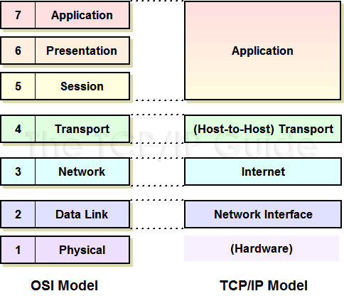
 Note: The internet and host-to-host transport layers are usually considered the “core” of TCP/IP architecture, since they contain most of the key protocols that implement TCP/IP internetworks.
 Key Concept: The architecture of the TCP/IP protocol suite is often described in terms of a layered reference model called the TCP/IP model, DARPA model or DOD model. The TCP/IP model includes four layers: the network interface layer (responsible for interfacing the suite to the physical hardware on which it runs), the internet layer (where device addressing, basic datagram communication and routing take place), the host-to-host transport layer (where connections are managed and reliable communication is ensured) and the application layer (where end-user applications and services reside.) The first three layers correspond to layers two through four of the OSI Reference Model respectively; the application layer is equivalent to OSI layers five to seven